
FTTH (Fiber To The Home) fiber-optic networks are a telecommunications architecture in which optical fiber is delivered directly to the customer premises. Today, this solution forms the foundation of modern telecommunications infrastructure, providing very high bandwidth, connection stability, and network readiness for further growth in bandwidth demand required by services such as gigabit internet access, IPTV, VoIP, and Smart Home solutions.
For an FTTH network to meet the requirements of both operators and end users, it is designed based on a clearly defined, multi-level structure. The appropriate network architecture determines service quality, infrastructure scalability, and long-term operational reliability.

The FTTH architecture is based on a logical division of the infrastructure into network layers, referred to as NE (Network Elements). These elements are responsible for specific functions – from national and regional data transport, through aggregation and distribution, to the delivery of the optical signal to the user’s end devices.
An FTTH network is designed using a hierarchical model comprising five infrastructure levels, designated NE1 through NE5. This division organizes network functions, simplifies infrastructure management and expansion, and enables optimization of capital and operational expenditures, creating a coherent and scalable transmission system prepared for the continued evolution of FTTH technology.
NE1 – Core Network
This is the highest level of the FTTH network structure and serves as the backbone of the entire fiber-optic infrastructure. It is responsible for transporting very large volumes of data between cities, the operator’s main nodes, data centers, and traffic exchange points, ensuring transmission continuity at both national and regional levels.
The core network is designed for maximum reliability, very high bandwidth, and route redundancy. The uninterrupted operation of all other FTTH network layers and the ability to simultaneously serve thousands of users depend on its stability. NE1 infrastructure is built using high-fiber-count optical cables, typically containing 144, 288, 576, or more fibers, as well as central office cabinets and passive components of the highest quality parameters. Connections are implemented using high-grade connectors, most commonly Grade B, ensuring minimal attenuation and high transmission stability over long distances.
NE2 – Aggregation Network
The aggregation network is responsible for collecting (aggregating) traffic generated by lower access network levels and efficiently transmitting it to the core network. At the same time, it provides distribution of the optical signal from the core network to distribution points serving large areas such as cities, districts, or residential neighborhoods.
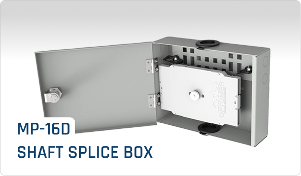
The aggregation network is implemented using medium – and high-fiber-count optical cables, most often containing from several dozen to several hundred fibers. This allows support for a large number of connections and provides adequate infrastructure reserve for future expansion. Feeder cables are terminated in closures, street cabinets, or cable manholes, and within a given area more than one distribution point may operate, significantly increasing the reliability and flexibility of the entire network.
NE3 – Access Distribution Network
This layer serves as the direct technical backbone for customer access connections and delivers fiber-optic services to local areas such as districts and their streets, residential estates, or individual buildings. It connects the aggregation network with the customer access network, enabling efficient distribution of the optical signal to points from which direct connections to end users are implemented.
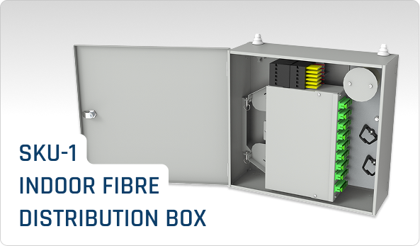
Within the customer access network, distribution points are located in the form of street cabinets, closures, or wall-mounted distribution frames, which remain the property of the operator. The structure of this layer is based on medium-fiber-count optical cables, most commonly containing 12, 24, or 48 fibers, allowing efficient resource management and flexible planning and deployment of connections. Within the NE3 network structure, a distinction is made between the feeder section and the customer access section, enabling a logical division of the infrastructure and rapid activation of new services without the need to interfere with the entire network.
The access distribution network also acts as a connection point for customers with higher transmission requirements, such as enterprises, public institutions, or critical facilities (banks, hospitals, government offices). At this infrastructure level, the operator’s network terminates, and the connection points located here constitute the locations from which installers deploy further segments of the customer access network, enabling the connection of new customers and the management of existing links.
NE4 – Customer Access Network – “Last Mile”
This is the lowest level of the network and is directly connected to the access distribution network. Referred to as the “last mile,” it covers the final section of the network whose purpose is to deliver the optical signal from the distribution point – more precisely, from the subscriber termination panel – to a specific customer premises, either to an optical outlet or directly to the user’s end device, such as an ONT/ONU (Optical Network Terminal / Optical Network Unit) or CPE/HGU (Customer Premises Equipment / Home Gateway Unit). This layer provides the physical connection of the customer to the operator’s network and constitutes the direct interface between the infrastructure and the end user.
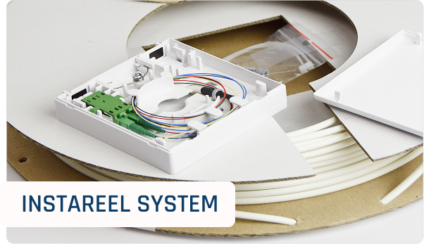
During the deployment of the customer access network, the quality of the components used and the precision of installation are of critical importance, as this layer has the greatest impact on connection stability and user experience. The NE4 network is built using low-fiber-count optical cables, typically containing from one to four fibers, with connections implemented using Grade D connectors. Within this layer, drop cables, bundles of subscriber cables, micro-duct solutions – particularly LFH (Local Fiber Hub) systems – as well as façade protections, seals, and aerial network components in the subscriber section are used.
NE4 / NE5 – ONT (Optical Network Terminal), Router, CPE (Customer Premises Equipment)
This layer represents the final level of the FTTH network architecture and simultaneously the termination point of the operator’s infrastructure at the user’s location. Depending on the adopted nomenclature, it may be referred to as NE4 or NE5 and includes all telecommunications devices installed at the customer premises that constitute the endpoint of the operator’s network and enable access to services such as internet, telephony, and television.
This group includes ONT (Optical Network Terminal) devices, routers, and other types of CPE (Customer Premises Equipment). Their function is to convert the signal delivered by the operator’s network – in optical form – into interfaces used by the end user, such as Ethernet, Wi-Fi, or RJ11 telephone ports. Fiber-optic patch cords connecting the subscriber outlet to the ONT form the last element of the passive infrastructure and close the entire transmission chain, carrying the signal from the core network, through successive distribution layers, to the user’s end devices.
Last Mile
The “last mile” comprises all elements of the customer fiber-optic network that directly participate in delivering the optical signal to the end user, together with the service access point. It is the lowest layer of the FTTH infrastructure and provides the physical connection of the subscriber to the operator’s network.
The last mile includes the network segment from the distribution point – together with its customer access section – to the customer’s end device, such as an ONT/ONU or CPE/HGU, or to the optical outlet within the user’s premises. Its purpose is to deliver the optical signal directly to a specific location while maintaining the required transmission and quality parameters.
A last mile network is built using low fiber count optical cables, typically containing one, two, or four fibers. It begins at the interface between the access distribution and customer access networks, i.e., at the NE3 level, more precisely within the cross-connection panel, where a dedicated subscriber termination panel is designated as the starting point for individual customer connections.
Why Is a Proper FTTH Network Structure of Key Importance?
The use of a multi-level FTTH architecture based on the NE1 – NE5 model makes it possible to build fiber optic networks that are not only efficient and reliable, but also easy to maintain and ready for further development. A well-designed network structure makes FTTH a long-term solution, providing operators with technological and business advantages in a dynamically changing telecommunications market, while at the same time reducing operating costs and improving customer service quality.
The key benefits include the ability to:
- increase network reliability,
- simplify management and maintenance,
- accelerate the subscriber connection process,
- reduce operational costs,
- prepare the network for future technologies and growing bandwidth demand.