fbpx

LOG IN

Please login to get an access to more data.

Fiber optic installation in Multi-dwelling buildings

To minimize the costs of network construction in multi-dwelling developments, previously built telecommunication infrastructure is utilised. This includes items such as dark fibres, cable ducts or pole foundations. Depending on local conditions, the distribution point and subscriber connection, various solutions are applied. What does the fibre optic installation with OPTOMER look like?

When building passive optical networks, it is essential to to consider the main task of the distribution point. Its role is to branch the fibers of cables arriving at the building from the telecommunications central office using optical splitters and connect them to the building’s vertical cabling.

Depending on requirements, as the distribution points the following products can be used: patchpanels or indoor/outdoor splice closures: MSP, PSP or PSPE, with capacities from 32 up to 576 subscribers, PSH-2 with capacities from 12 to 144 subscribers and PPU cabinets or PSS, MSS poles, with capacities starting from 12 subscribers. To reduce the number of splices in the optical path, splitters can be spliced with subscriber fibers using PRW boxes inside buildings or MSS poles outside.

Network plans AND PRODUCTS USED FOR CONNECTING THE CUSTOMER

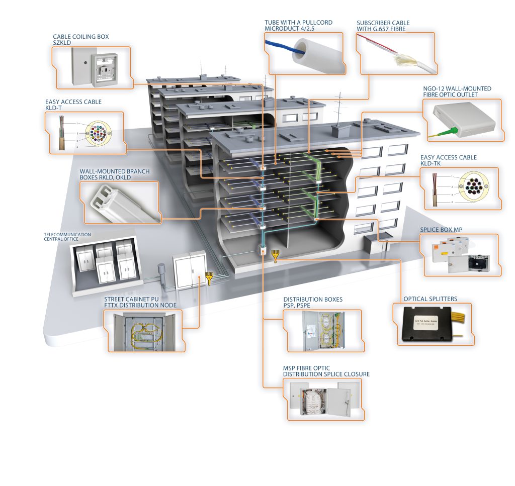
In multi-storey buildings, one of the most optimal solutions is vertical cabling using easy access cables. These cables are characterized by a mechanically resistant outer sheath and loosely arranged optical fibers. This design allows individual fibers or modules to be extracted through windows cut in the cable sheath.

Easy access cables are offered in two versions: KLD-T – with individualy buffered fibers (ability to extract up to 20m of fibres), where each individual fibre is in an easy strip 900μm buffer tube, or KLD-TK – modular (with the ability to extract up 6m of module), where fibres are grouped in a single compact (modular) tube in numbers of 2, 4, 6, 8, 12 fibres per module. The window cutout in the vertical cable is secured with an RKLD branch-off cover, a wall-mounted NSP-1 floor box, or an MP-16 duct closure. The cutting window in the vertical cable is protected by a branching box (RKLD) or shaft splice box (MP-16 or NSP-1). By using fibres with 900μm tubes, to ensure the possibility of connecting clients on the top floor of the building, the SZKLD easy access cable coiling box is installed at the end of the cable, storing a reserve of approximately 20m of fibres from the easy access cable.

Network Architecture for Access Networks in Multi-Family Housing Estates
CONNECTING THE END USER TO THE FIBER OPTIC NETWORK

Connecting a subscriber depends on the type of cable used. Using a cable with single fibres in 900μm tubes involves pulling the chosen fibre though a window cut in a cable outer sheath and pulling it through a microtube laid from the window in the cable to the customer optical outlet (NGO-12).  The microtube can be equipped with a pullcord to facilitate fibre installation. A pigtail terminated with an SC/APC connector is spliced to the fibre in the outlet.

When using cables with multi-fibre compact tubes, clients are connected using pigtails with increased mechanical strength. The pigtails are spliced with the fibres of the compact tube pulled through a window cut in the cable outer sheath, and then distributed to client outlets. Floor splice boxes are installed in place of cut windows. To make the installation faster and easier, OPTOMER offers outlets with reinforced factory-installed pigtails at lengths tailored to customer needs. (e.g. 35m)

The article was created with the participation of experts from the OPTOMER’s R&D Department. We encourage you to check other access network solutions.

Skip to content