fbpx

LOG IN

Please login to get an access to more data.

Applications of Passive Optical Components in Telecommunication Networks

Fibre optic cable is a fundamental component of modern fixed telecommunication networks. A typical fibre optic link consists of two optical fibres, with transmission at a single optical wavelength, most commonly 1310 nm or 1550 nm. One fibre is used for transmission in one direction and the other for transmission in the opposite direction. The transmission speed is limited to 400 Gbps due to transmitter and receiver limitations.

Typical telecommunication link
Fig. 1 Typical telecommunication link

The growing demand for bandwidth goes hand in hand with the need to reduce costs and simplify the transport layer of the network infrastructure. In such scenarios, fibre-optic- based telecom networks deliver outstanding performance by enabling the transmission of multiple services and achieving total throughput in the range of terabits per second (Tbps). To increase the efficiency of individual fibres, multiplexing technology is widely used, sharing the fibre optic medium among many end users.

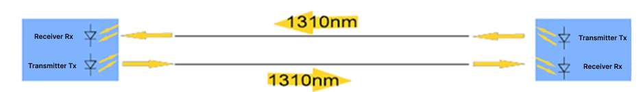
Time domain multiplexing, performed on electrical signals, combines several lower bit-rate signals into a single higher bit-rate data stream, which is transmitted over a single data link. In this case it is necessary to use active multiplexing and demultiplexing devices.

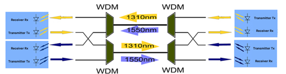
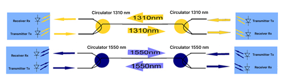
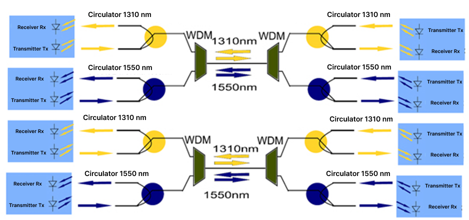
An alternative to time-domain multiplexing is optical multiplexing, which involves transmitting multiple optical wavelengths over a single fibre. The basic advantages of optical wavelength multiplexing include: high reliability achieved by the use of passive optical filters, no need to use electrical power supply and no costs of energy consumption, very quick implementation. Among the main advantages of optical wavelength multiplexing are:

  • high reliability achieved through the use of passive optical filters;
  • no need for power supply and thus, no energy consumption costs;
  • rapid implementation.

The disadvantage of such a solution is the addition of insertion loss to the transmission link, ranging from 1 to 4 dB. The highest transmission rates are achieved through the application of Wavelength Division Multiplexing (WDM) technology, which enables the transmission of multiple optical wavelengths in the range from 1260 nm to 1675 nm over a single optical fibre. Older optical fibres often have more hydroxyl (OH) ions, causing increased attenuation, the so-called “water peak”, specifically around 1380 nm.

Two fibre optic links implemented with Wavelength Division Multiplexers and a pair of optical fibres
Fig. 2 Two fibre optic links implemented with Wavelength Division Multiplexers and a pair of optical fibres

The multiplexing process is carried out using passive optical devices such as WDMCoarse WDM (CWDM), or Dense WDM (DWDM) multiplexers/demultiplexers. The basic differences between the systems are the number of optical transmission channels and the spacing between them. A WDM is the simplest device that allows the transmission of two optical wavelengths, most commonly 1310 nm and 1550 nm. These are the most frequently used optical wavelengths in telecommunication equipment. CWDM accommodates up to 18 distinct channels over the wavelength range of approximately 1270 to 1610 nm. Typical channel spacing in CWDM is 20 nm. Due to the large channel spacing, basic WDM and CWDM are considered the cheapest ways to increase the capacity of fibre optic networks. DWDM employs narrower spacing between wavelengths compared to other multiplexing methods, such as basic WDM and CWDM. Typical channel spacings in DWDM are 0.8 nm or 0.4 nm. This is accompanied by significantly higher costs for optical devices, but it provides a very high transmission capacity per single optical fibre, reaching rates of multiple terabits per second (Tbps).

Another way to increase the capacity of an optical network is to use optical circulators. They enable the transmission of two optical wavelengths with the same length in opposite directions over a single fibre. They make it possible to transmit two optical waves of the same wavelength in opposite directions in a single optical fibre.

Two fibre optic links implemented with optical circulators and a pair of optical fibres
Fig. 3 Two fibre optic links implemented with optical circulators and a pair of optical fibres

This is a particularly interesting solution due to the fact that it does not require any reconfiguration of active devices or wavelength conversion. Two circulators, one at each end of the transmission link, create a bidirectional channel over a single fibre. The service that has so far been transmitted over two optical fibres can now be transmitted Circulator 1310 nm over a single fibre. Adding extra WDM multiplexers to the system enables the transmission of two services over a single optical fibre.

Four fibre optic links implemented with optical circulators, WDMs and a pair of optical fibres
Fig. 4 Four fibre optic links implemented with optical circulators, WDMs and a pair of optical fibres

In some applications, the capacity of a single optical channel significantly exceeds current demand, thereby allowing multiple users to share the same channel. Passive optical networks implement this approach, which significantly reduces network infrastructure costs. Building individual two-fibre links from the central office to each subscriber would not be economically justified. Shared access to the transmission medium is an effective solution. The optical signal is delivered via a single optical fibre to a group of users and then distributed among them using a passive optical splitter.

PLC Splitter in a Passive Optical Network
Fig. 5 PLC Splitter in a Passive Optical Network

An optical splitter divides the power of the optical signal transmitted from the central office and distributes the data stream among the end users. All end users receive the same information, while the end user’s modem, identified by its specific physical address, receives information intended exclusively for that user. For upstream transmission, the splitter enables signals from individual end users to be combined onto a single optical fibre, with each user assigned appropriate time slots for transmission.

Passive optical devices, when appropriately selected for a given application, do not alter the information transmitted by the optical signal and offer a cost-effective alternative to expensive active devices or deploying new optical fibres.

Skip to content